0

Rubber Lined Piping & Engineering Manufacturing Procurement Process Challenges

EPC

Doing a large project for engineering firms can be rewarding and challenging depending on the contract at the same time. Here are some of the process challenges with rubber lined piping and piping projects in general.

The most common way to price many short lead, large scope projects is to bid a Bill of Material. These BOM’s are generally generated form a snapshot of their CAD system model. The CAD bill of materials unfortunate provides the first challenge such as how to price 10,000 feet of pipe when you don’t know the individual lengths? How many termination are there, how many branches are there, supports etc…? The descriptions of the piping will say rubber lined grooved. So to determine the quantities of grooves you must sometimes estimate based on the coupling count.

Some of these challenges have been overcome by providing welding rates, cutting rates, branch rates etc… This method of pricing does not provide the purchasing groups a clear cost on the project. As many of the welds and cuts do not get rolled up or counted into the price. The preferred alternative is to price a- la cart. This style of pricing would mean that any flange price listed for example in the BOM would include all the shop processes required to fasten a flange for example to any piece in the system. This provides a transparent all in fabrication price.

Assuming your prices are competitive and you won the contract, the next challenge is that generally the fabrication drawings are not complete. Hopefully the purchasing people will allow you to purchase the BOM as it stands, as waiting for drawings can delay projects, while the drawings are being completed you can purchase and stage your materials for fabrication. Next arrives the drawings and they pose their own problems as discussed in my blog on cad challenges.

Now you fabricate your rubber lined piping. When you ship your project to site you are not shipping flanges pipe and a branch separately. You are shipping a spool that contains all the materials listed in the BOM. Reconciling the original PO is extremely difficult as the original PO is based on a BOM. Depending on the purchasing team a backup document containing the price breakout of the spool may becomes a useful tool to reconcile the billing on the spool i n order to eventually consolidate the project purchase order at the ends

Keeping these interesting challenges in mind and discussing the challenges with an agreement ahead of time, before the issue of a purchase order will ensures a smooth trouble free contract.


0

Rubber Lined Piping Systems and your Cad System

14

Modern Cad systems can be problematic for rubber liners….

1 Cad people may not take into account the rubber gasket on the face.

Normally when an engineer lays out the piping system they choose many different ways for the software to dimension the Isometric.

Long run dimensioning – Dimensioning from intersection to intersection, this is ok if you let the fabricator interpret the spool lengths. Generally the pipe lengths get indicated but the rubber lined face gaskets are not taken into account, groove type gaps or the fitting dimension are incorrectly setup. The other common mistake to this style of dimensioning is that the travel exceeds the physical manufacturing limitation of the spools in between.

Spool dimensioning -Dimensioning to the center of all the joints- This is by far the best method if the model is setup correctly. Grooves should be modeled not just specified, as the tolerance of this should be taken into account (1/8″ rubber on the face of the groove as well). The biggest challenge becomes when people use stock grooved libraries for non rubber lined product for a rubber lining system. The addition of the face rubber increases the fitting dimensions.

2 Descriptive modelling

As most modern advanced Cad systems such as Bentley, Aviva, Integraph or Microstation are very ridged and are provided with a standard parts library. For example many rubber lined systems end up being a coupled system. When using auto routing for piping, rules are set for spool lengths and gaps. A common cheat is to describe the piping as piping with grooves and to download the spool separations to the manufacturing. The result is that most spools in this case will have to be redrawn by the manufacturer as opposed to processed using Spoolgen for example. The redrawn spools may not always conform to the design dimensions making drawing checking and receiving of final product very difficult.

3 Libraries built for a steel only system.

All cad systems in the market are built to accommodate steel fabricated systems. So there are always compromises when it comes to descriptions and dimensions. As a rubber lining supplier it is very cost prohibitive to create libraries for all the engineering systems. Currently  some coupling system companies have up to 23 different software catalogues built so that engineers can use their products.

4 Specifications do not always contain the compounds or thicknesses.

When processing Isometrics a specification a line class is usually provided. Some time these are very well laid out for rubber. Other times it is a combination of pipe sizes, service and line class that will determine the lining. The lining information is often not contained on the Isometric itself. Depending on your cad team this can be a difficult item to interpret from the information provided.

Conclusion

The sooner you can get involved in a project the better. Working with the engineering firms, understanding their challenges and concerns will help you find common grounds. Working with both the EPCM and end users will reduce processing errors, reduce the overall project lead times and cost.


0

Soluble Salts Testing

Soluble_Salt_Meter_Working-resized-e1367233453953-237x220

Soluble Salt testing is becoming the latest inclusion into EPCM specifications for quality requirements.

What are Soluble Salts and Sulphates?

Soluble Salts and Sulphates are the most dangerous forms of contaminants for paints and coatings. When they are painted over they have the power to draw moisture through Osmosis and cause blistering, detachment and accelerate corrosion of the underlying metal. When steel is repainted, rough or pitted areas are visible after dry abrasive blast cleaning. These may contain soluble salt contamination, especially in the base of the pits. Dry abrasive blasting does not remove these salts. It is wise to check for the presence of soluble salts with specially designed field test kits before painting and if they are present in detrimental amounts, to take additional cleaning steps to remove the salts.


How can you test for Soluble Salts?

The common tools used to test for soluable salts are the Chloride Iron Test Kit for Surfaces. This test looks for remaining chloride levels on a sub-straight prior to painting. The second tool is a Salt contamination Meter. This tests for soluble salts on the substrate surface prior to painting by absorbing distilled water soaked filter paper and then testing it.


How do Soluble Salts Occur?

There are many ways your steel can be exposed to soluble salts and sulphates. The most common way is through transportation. Pipe and steel travelling at sea can accumulate contaminants during travel to the fabricators. The other method is when trucking materials during the winter. Road salts can easily be distributed on to steel during the transportation process.


Is checking for Soluble salts necessary?

Soluble salts became an additional test required and recommended by Nace.  As engineers attempt to cover off as many concerns with their specifications as possible, it is becoming a popular addition. The method of testing and the frequency required by this code make production volume of pipe spooling and steel testing costly and difficult. Most pipe from mill come with mill varnish helping protect the surface during travel. New steel will generally not be pitted, where a good sandblast profile will easily eliminate any surface contaminants. There are situations where you are on an oil platform, recoating old steel, in the middle of the ocean where this specification is highly advisable but for most steel processing this is considered over processing. The short answer is where required.


Soluble Salt in relation to rubber lining.

Generally speaking in a rubber lining application, the internal liner will fail far sooner than the steel or coating will deteriorate. Rubber lined product is generally considered a wear product. Warranties are difficult as process flow, materials configurations are always changing. Unless adamantly specified this specification should be avoided.


0

Storing Rubber Lined Equipment

IMG00266-20140122-0919


ALL-WEATHER STORAGE

1.   Rubber linings should never be exposed to direct sunlight or direct outdoor weathering, for periods longer than a few days.   All other linings should be protected from sunlight. If no other alternatives are possible, linings should be periodically painted with Age Guard.


 SUMMER STORAGE

1.   If possible, store in shaded areas away from direct sun exposure.

2.   Paint outside of tanks with aluminum or white paint, or cover with a tarpaulin.

3.   Closed tanks should be kept ventilated.

4.   Tanks to be stored for long periods after having been in service, should be partially filled with a diluted solution of the chemical they were designed to contain (a 1-3% concentration probably will be sufficient).

5.    For piping, the ends to be capped at all times before going to service.  Helps protect against the weather and damage that may occur on site


 WINTER STORAGE

1.   Equipment should be protected as much as possible from the elements by covering with tarpaulins, erecting temporary shelters, etc.

2.   Tanks containing solutions must be emptied if temperatures drop below the freezing point (of the solution contained therein).

3.   Equipment should be handled very carefully and protected from subjection to external forces (sudden blows, flexing, twisting, etc.). Sudden temperature changes also are to be avoided. These precautions are most important for linings with a hard durometer.


 IDLE OR STANDBY EQUIPMENT STORAGE

1.   Idle or standby equipment (especially semi-hard lined) should be protected against excessive drying out and temperature changes. The best way to accomplish this is to fill the tanks with a 1-3% solution of acid, preferably H2S04, and hold at ambient temperature. This will help keep the lining more flexible and minimize the expansion and contraction problem as well as decrease the possibility of thermal shock when the equipment is put back into service.

2.   If the diluted solution is not optioned, then apply Age Guard to the rubber linings once per year the lined equipment is idle.***Note: All idle equipment should be inspected prior to being put into service.


Any questions please contact RubberSource @ 519-830-0546 / buck@rubbersource.ca

Rubebrsource

Buck Meadows / Rubber Technologist

Technical Sales Manager

RubberSource


0

How to compare rubber compounds for slurry applications.

evaluation

Rubber specifications are confusing and some of the properties described in some specification sheet do not help evaluate the wear characteristics of the compound.

In fact most of the time the important lab tests, which tell you how well a rubber will perform in a slurry application are left out.

Specification sheets contain many characteristics which are elemental by definition. In other words the fact that the rubber is tan in color has no relevance to the actual wear “the undesirable mechanical removal of material in fine particle from from the surface.”

Here are some of the common specification criteria and their relevance.

Durometer: (Elemental Property)

In a slurry wear application the fact that a rubber is softter than another may indicate that it may be perfom better or worst but that would be opinion. Harder compounds generally perform better under cut and chip situations but there is a lab test for cut and chip as well as wet sliding abrasion. Durometer is not really the deciding factor. This rubber just happens to be a given duro shore A.

Tensile Strength: (Elemental Property)

Tensile strength is very useful when comparing rubberized tracks and track pads for tanks. As the ability not to rip apart is important. When comparing an elastomeric lining which is adhered to a steel sub-straight it’s tensile strengthen is not relevant factor in this application.

Ultimate Elongation: (Elemental Property)

Going back to my previous example when a snowmobile takes off  the ultimate elongation is very important so that engineers and designers can calculate if this track will perform correctly. In a rubber lined wear application this factor is not relevant. It will never achieve it’s ultimate elongation adhered to a metal sub-straight.

Specific Gravity: (Elemental Property)

This is the actual density of the product. In the olden days the buoyancy of rubber was a good indicator of how many rubber fillers were in the product. Floating rubber was regarded as good rubber. Dense rubber was thought to have more clay which would adversely affected it’s wear performance. This day and age with material sciences helping to improve material quality, adders like carbon is common. Carbon increases wear characteristics in some cases. Therefore the specific gravity is simply that, what it’s density is. Not a good wear performance indicator.


Performance properties are “Real factors which can be tested and directly speak to the wear performance in a slurry application.”


Cut and Chip: (Wear Performance Property)

Cut and chip is a test performed in a lab where you can accurately compare compounds and find which is the best in a cut and chip application. This is completely relevant when you are trying to increase the longevity of a liner in a slurry application. This was a test devised by BF Goodrich in order to evaluate how good the tires would perform on the road. A very good indicator of wear life.

Wet Abrasion: (Wear Performance Property)

A test to determine the exact resistance in wet abrasion. It’s a sliding plate that cycles on the rubber in a container of a known wear slurry and the removal of the material is then measured to determine is wear performance characteristics. This is very relevant to wet sliding abrasion test to determine the rubber wear.

Water Resistance: (Wear Performance Property)

Also known as the percentage of swell. The reason this is important is the amount of swell will adversely affect wear within certain services such as acid. The more a rubber will swell the less it will perform in that situation.

Resilience:(Wear Performance Property)

The ability to return to it’s original shape is a huge factor in determining if this rubber will be suitable for wear. The more resilient the better the rubber will perform in a slurry application.

Tear (Die C):(Wear Performance Property)

This is another important performance criteria as the ability for the rubber to hang on to the straightaway is important. This is a relevant value when considering rubber for slurry wear applications.

Conclusion

Rubbers with high Cut an Chip resistance and Wet Abrasion resistance will perform better in wet slurry application. Elemental properties such as density are interesting and mater of fact but should not be deciding factors when choosing rubber compounds for wear applications.


0

Shelf Life Of Uncured Protective Rubber Linings

Commercial-Grade-Rubber-Sheet

In determining the shelf life of uncured rubber linings, several instances but be understood:

  1. The level of heat memory built into a compound (ex. Synthetic Rubber takes more heat to break down than a Natural Rubber)
  2.  The lower the storage temperature, the longer the rubber lining will be useable.

As a rule of thumb the average uncured rubber linings (NR, IIR) will have a shelf life of approximate shelf life of 9 to 12 months if stored at a temperature of 10°C (also out of sunlight).  If the linings are stored at a lower temperature the rubber lining will much longer the 12 month period.  Please note that Neoprene (CR) and Nitrile (NBR) compounds have a typical shorter shelf life than the above mentioned compounds.  In dealing with these compounds a great of caution is to be used as they can cure much faster.  If storing rubber at a lower temperature that the recommended 10°C  the rubber may become frozen, if this was to happen the roll will need to be unrolled and left at an ambient temperature for 2 weeks to thaw the rubber.  After the 2 week interval the rubber will need to go on a hot table to help facilitate any shrink that might of occurred during the freezing process.

Any Questions please contact RubberSource @ 519-830-0546.

Rubebrsource


Buck Meadows / Rubber Technologist

Technical Sales Manager

RubberSource

0

Flange Bolting Specification For Rubber Lined Pipe

flanged-torque-sequence

Suggested Methods and Guidelines for Torquing and Bolting Flange Joints

 1) Bring mating flanges into contact and install bolts, Torquing nuts “finger tight”.

2) Align pipe and adjust bolts to produce a uniform gap between the flange faces.

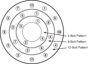
3) Torque two opposing bolts to 1/2 the full torque suggested for the pipe size being

4) Repeat step 3 for the bolts nearest 90° to the first bolts torqued.

5) Continue Torquing opposite pairs of bolts until all bolts have been tightened.

6) Repeat steps 3 through 5 until all opposite pairs have been torqued to the full value

suggested for the pipe installed.

Pipe Size (Inches)         Bolt Size         Bolts    Half Torque (Ft-Lbs)   Full Torque (Ft – Lbs)

2                                  5/8                   4                                  6                                  12

3                                  5/8                   4                                  8                                  16

4                                  5/8                   8                                  6                                  12

6                                  3/4                   8                                  9                                  18

8                                  3/4                   8                                  12                                24

10                                7/8                   12                                13                                26

12                                7/8                   12                                18                                36

14                                1                      12                                25                                50

16                                1                      16                                23                                46

18                                1 1/8                16                                25                                50

20                                1 1/8                20                                23                                46

24                                1 1/4                20                                34                                68

30                                1 1/4                28                                32                                64

36                                1 1/2                32                                44                                88

42                                1 1/2                36                                50                                100

48                                1 1/2                44                                49                                98

60                                1 3/4                52                                69                                138


Practical Method Used to Prevent Over Torquing Gasket and/or Face Lining Rubber

A.Mechanical steel ring stop or non-compressible gasket properly chosen to limit

compression to 25% on the rubber lined flange joint.

• When soft rubber lined flange face is used as gasket, the rubber lining

should be brought up to 1/32″ of bolt hole.


  1. The use of a full-face, fully cured gasket, somewhat softer than the rubber on the

flange face. This gasket takes the bulk of the compressive distortion, minimizing

problems to the flange lining. This method is mandatory when hard rubber is used

in lining pipe.


Over-Compression of Rubber Lining on Flange Surface

 • Rubber in compression by over-stressing it beyond the elastic limits will

• A mechanic in an attempt to obtain leak free performance will excessively

over-tighten the bolts to prevent their loosening.

• Under dynamic loading, the over-compressed rubber fails by tearing and

cracking at outer edges of flange.


Problems That May Invalidate the Use of Specific Torque Numbers

In general, it is not a good idea to specify bolt torque for tightening rubber gaskets

on flanges. Torque can vary over a 2 to 1 ratio. Some reasons are:

• Improper procedures used for torquing bolts.

• Flange may not be true so as to prevent misalignment of one end. Bending

stresses are high when bolting up to pull the flange back in line.

• When flaring out the throat lining over the full face of flange, there may

be excessive stretching and thinning of the rubber. This will not allow

positive or even compression on the rubber when attempting to seal.

• High low spots on flange and condition of bolts.

• Rubber surfaces on flanges are normally coated with various lubricants,

etc. This alone can neutralize all the efforts spent upon specifying torque

• It is better to use a more practical method of using non-compressible

gaskets, etc.


 RUBBER LINED FLANGE ASSEMBLY PROCEDURES

Care shall be taken to ensure that the rubber lined flange is not damaged by being cut or crushed during assembly. The rubber lining on a flange must not compress more than 1/3 of its thickness or the lining could tear away from the metal surface, causing a leak. Listed below are recommendations and procedures for gasketing and bolt tightening rubber-lined pipe, flanges, and equipment.

Use of a gasket is preferred in order to prevent damage to the rubber lined flange face if future removal of the pipe becomes necessary. The gasket thickness should be equal to or slightly less than the rubber lining, but not less than 1/8 inches (3.2 mm) and is also advantageous to protect the original lining on the flange face if the connection is ever dismantled. The gasket hardness should be equal to or slightly less than the hardness of the rubber lining, but not greater than 60 (Shore A). Generally Neoprene, Butyl, or EPDM makes a good gasket material. However, the gasket material should be selected based on the service conditions. The gasket Durometer should be in the 60 Shore A Durometer range. Technically a new gasket should be used after disassembly because the gasket takes a compression set and it is virtually impossible to replace it in the same position. The surface of the lining in contact with the gasket should be treated with a release such as never seize or water base silicone solution, which will allow disassembly without causing damage to the lining.

1) To provide gasket release, we recommend a release agent be sprayed or painted

on the pipe of flange joints. They are various commercial agents on the market.

One we find to function well is Never Seez.

2) Use a star pattern to tighten. All bolts should be initially tightened until they are

3) Then each bolt should be torqued down to 15 ft-lbs. using standard cross pattern

4) Recheck the torque after 4 to 6 hours to ensure that there is a uniform positive

pressure on the assembly.

5) After 24 hours, bolts should be checked to ensure that 15 ft-lbs is maintained.

6) After the line or equipment is put in service, someone should check to ensure that

there are no leaks. If a leak is observed, the bolts should be tightened evenly and

only enough to stop the leak, over tightening the rubber lined flanges will damage the rubber lining inside where the pipe and flange meet and tear the rubber on the flange. All the precautions and directions above must be followed.


RUBBER LINED FLANGES

On flange faces for pipe man ways and/or outlets we recommend the following:

30 to 70 Shore A Durometer Linings

For linings with a Shore A Durometer of 35 to 49 it is recommended to use a full-face fiber gasket. For 50-70 Durometer linings use the lining material itself on the flanges, no additional gasketing is required. For linings of 71 and above it is recommended to use a 60 Durometer EPDM or Neoprene gasket.


Semi-Hard or Hard Rubber Linings

Semi-hard or hard rubber linings have a tie gum and are not recommended for flange faces. It is best to purchase and use semi-hard or hard ebonite lining material without tie gum on flange faces. The hard rubber is non-compressible, and when torqued, it retains its strength. Linings of the hard rubber variety, with tie gum, squeeze out when over torqued, and the hard rubber cracks on the inside radius.


Assembly Recommendation

1.) Assemble using 15-20 foot pounds of torque. Use a star pattern to tighten, and it is

best to recheck the torque after 4 to 6 hours to ensure that there is a uniform positive

pressure on the assembly.

2.) In all cases for pipe assembly a 1/8″ rubber gasket to provide a seal is recommended,

and is also advantageous to protect the original lining on the flange face if the

connection is dismantled. Generally Neoprene, Butyl, or EPDM makes a good gasket material. However, the gasket material should be selected based on the service conditions. The gasket

Durometer should be in the 60 Shore A Durometer range. Technically a new gasket should be used after disassembly because the gasket takes a compression set and it is virtually impossible to replace it in the same position.

3.) To provide gasket release, we recommend a release agent be sprayed or painted on

the pipe of flange joints. They are various commercial agents on the market. One we

find to function well is Never Seez.


Any questions on bolting flanges please contact me RubberSource @ 519-830-0546.

Rubebrsource


Buck Meadows / Rubber Technologist

Technical Sales Manager

RubberSource

0

General Call for Rubber Lining Industry Suppliers Articles!

articles-icon2

Rubber Lining.org is a site dedicated to being the repository of knowledge for the rubber lining industry.

We welcome articles from professionals in the rubber supply, rubber  lining, piping, engineering and wear industry. We will publish all articles related to rubber lining and associated information as long as they are written by rubber lining industry professionals who wish to contribute to this knowledge base and given that the articles are non-partisan.

If your company contributes an article you will get credit for the information as well as get listed under one of the vendor tabs at no cost.
If you wish to submit an article please e-mail it to.

Dan.chamberland@Rubberlining.org

Thanks

0

Bromobutyl Rubber Linings

uncured-bromo-butyl-scrap-rubber-waste-sheets-300x194

Bromobutyl is a derivative of the halobutyl family, which is structurally similar to chlorobutyl rubber and produced through the same halogenation process: Brominated (BIIR) to Chlorinated (CIIR). By using the brominated process allows the same workability in the lining as a chlorobutyl.   The Bromobutyl polymer will exhibit stronger physical characteristics over Chlorobutyl. Bromobutyl Linings are either blended with Natural Rubber for ease of application or made pure in polymer content, which means there is no other polymer in the formulation which gives the lining stronger permeation and heat resistance.


Advantages

•    Tight knitting of the molecular cross link which results in an extremely low permeability rate.

•    Low glass transition temperature

•    Wide vulcanization versatility

•    Fast cure rates

•    Higher Heat Resistance

o   Other Bromobutyl linings have a maximum heat resistance to 121°C as to the pure bromo can run at a constant temperature of 127°F and handle spikes up to 150°C

•    Stronger bond strength to substrates

•    Excellent Oxidation / Ozone Resistance

•    Good Abrasion Resistance


Common uses of Bromobutyl linings are:

– Scrubber Towers

– Piping,

-Storage Vessels

– Chutes

– Thickeners / Clarifiers


Any questions on our Bromobutyl linings please feel free to contact

Rubebrsource

Buck Meadows / Rubber Technologist

RubberSource

Ph# (519) 620-4440

Email: buck@rubbersource.ca

0

Sandblast for Rubber Lining and Painting

images

General Sandblasting Information for Code Rubber Lining and Painting

Before beginning any kind of blasting you must verify that the humidity and dew point are at acceptable levels. Not respecting the proper dry bulb wet bulb parameters will only lead to flash rust. This is generally not accepted in the coatings industries and can cause failures between the sub straight and the adhesives. There are charts available to understand this phenomenon and will help you find the acceptable ranges.

The second evaluation most codes require you to do, is to perform a blotter test. A blotter test is usually with a white cotton or white cloth testing that your air is free from oil, contamination or water. Given you have a modern, proper blasting or painting system with an in line air water separator and filter system you can be assured that this test is to reassure your customer that your air is good.

Adding oils and water to a blasted surface will negatively affect the adhesives and the overall performance of the liner.

There are other blast tests required for some specification, such as the soluble salts test. Although this test comes up on occasion, for most rubber lining it is not required. We will cover this subject in another post.

For the lining of steel pipe, tanks and other steel sub straights, you must achieve a blast profile of at least SSPC-SP5 classified as a white metal blast.

There are visual charts such as the example below to visually compare. These also have detailed descriptions to evaluate the blast achieved.

Nace

In addition to getting the surface clean you must also provide a profile for the adhesive. You can verify the profile of blast using a Testex strip shown below. This is a common way of evaluating the sandblast profile and proving to your customer the work was performed to specification. This is by far the most important part of the blasting process. Sure, cleaning scale, mill varnish is important, but in order for the adhesive to properly hold  the liner in place, the tooth or profile will give the adhesive a larger surface area to hold onto. Very important.

download

Blast profiles need to be a profile of 3-5 mils for adhesive as it is required for good surface adhesion. For a paint anywhere from 1.5-4.5 mils is acceptable depending on the specification provided. 

If you glass bead a surface you will get a nice finish, looking like SSPC SP-5 but your adhesion will be terrible due to the profile being flat. You can effectively double your adhesion surface by blasting a proper profile.  Achieving the correct  profile has everything to do with your blasting media and once you find the correct blast media and pressure you can achieve this result 100%of the time. Many option of blast media will create this profile.

For painting the exterior of pipe and tanks most specification call for SSPC SP-6 which is classified as a commercial blast.

The profile for paint is important but not as critical as for adhesives.

Once the proper blast profile has been achieved, adhesive needs to be applied before flash rusting can occur. A good rule of thumb is within 20 min, environmental conditions affect this time one way or another dramatically. On a dry sunny hot day with no humidity the piece can stay without adhesive longer with no risk of flash rusting.

If you have followed all of this you will have an excellent base for which the adhesive can be applied.